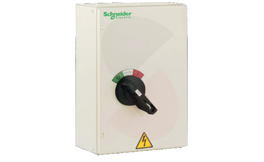
Isolator Panel

Isolators are used in electrical installation to MAKE, CARRY and BREAK circuit current. The isolators ensures that there will be no current at the load side even if impulse voltage appears when the isolator is OFF.
Salient Features
- Whether proof type
- Sheet steel enclosure
- Conforms to EN/IEC 60947-3
- Suitable for AC22-A and AC22-B utilization category.
- Available in DP, TP, and FP versions in 40A, 80A & 100A ratings
- Finger proof terminals-IP20
- Short time withstand capacity: 756A, 1 sec
- Degree of Protection: Upto IP-66
- Applications: Chillers, Air Conditioners and Motors / Weather Proof.
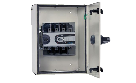
Changeover Switches(63-2000A)

C-Line offers you a unique series of changeover switches combining compactness with high performance & customer convenience, thus, making C-line a state-of-the-art product in changeover technology.
The C-line range covers ratings from 63A to 2000A in 6 frame sizes. These change over switches are available in open execution, sheet steel enclosure, fused version(Suitable for DIN type fuse-link) and motorized version.
Onload changeover S-D consists of two separate sets of terminals for incoming supplies and a set of output terminals to connect the common load. Thus, changeover switch ensures continuity of supply to the load by alternating between normal and alternate supply.

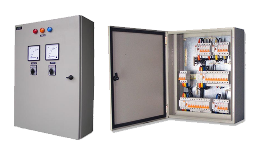
General Control & Synchronization Panel

Synchronizing panel will operate on an automatic mains failure system, so that when the main supply is interrupted on one or all phases (after an adjustable delay period) the generator sets will start-up together. After an initial warm-up period (adjustable) the generators will synchronize with each other by means of motorized circuit breakers or contractors onto a common busbar. Next, the motorized change-over switch will be closed and the load will be connected to the main distribution box.
The load share units continuously monitor the load and during low demand periods one or two generators will be shut down to save on fuel consumption. As demand rises again the second generator and third generator will be restarted, synchronized and reconnected to the load. When the AMF control unit detects that the main supply has been restored an adjustable observation period is activated before the main supply is reconnected. A cool down period will then follow, after which the generator sets will be shut down.
A Synchronizing Panel works between two or more different power sources like DG sets to manage power supply. Synchronization helps in making different DG sets behave as a virtual single unit and eliminates subdivision of total load. It helps in transferring load from one unit to another as during service period, so that the unit requiring service can be easily shut off. In this way the critical load need not be interrupted and there is no production loss. During low load we can run any single unit, and synchronize more units as the load increases. This can be manual or automatic
Key features of General Control & Synchronization Panel
- 3-pole or 4-pole system as required
- Various combinations of load transfer by ACBs, MCCBs or Contactors
- Protection class up to IP 54
- Load sharing/load shedding
- Automatic and manual synchronizing
- Factory built to client’s specifications
- Ratings up to 6000A
- Control functions available for engine monitoring, warm-up and cool down periods, emergency shutdown, multi attempt engine start control, engine test runs
Two Types of Motor control Centers
a.Fixed
b.Draw out
Fixed:-
With all low voltage applications necessary in large industrial sites, large commercial buildings and infrastructure with fixed design. Completely centralized and modular motor control, using state-of-the-art Schneider Electric components: conventional and intelligent Motor control centers (MCC), variable speed drives and soft-starters. Power factor and harmonics compensation, with Schneider Electric capacitors: high performance, high safety and long lasting installation, by design.
Draw out:-
The Mw2 column satisfies the motor control needs of exacting processes. The new withdrawable drawers with their integrated front face require no tools to handle them. Tests and maintenance operations are simpler and quicker. Column compactness means that more equipment and functions can be concentrated into the same space, thus reducing the total number of columns. With the new Mw2 column, you optimize the cost of your installations. With new Mw2 column of the same size, you can now install more motor feeders. The Mw2 column allows a combination of functions, for example motor and distribution incomers and feeders.

Feeder pillars or lighting control Panels

Feeder pillar or Lighting Control Panels are manufactured in galvanized/electro galvanized steel sheets or aluminum sheets. Single wall and Double wall constructions are available on request and are available in 4 / 6/ 8 way distribution. These include instrument panel with voltmeters, ammeters, service fuses and selector switches. The built, structure and designs are suitable to all kinds of lighting applications.
Feeder pillars are manufactured using Weather Proof (GRP) Enclosure with rating of IP-66 suitable for Internal & External applications. These include instrument panel with service fuses and selector switches. The built, structure and designs are suitable to all kinds of lighting applications.
Key features of Feeder pillar or Lighting Control Panels
- Designed for internal & external applications.
- 630A main busbar rating.
- Offered in single/ Double walled aluminum or GRP enclosures
- Index of protection : IP 55 & IP 65

Capacitor Banks

Capacitor Banks improve the power factor by adding capacitive reactance in steps as per the power factor requirement.
Low Voltage Power Factor Correction Banks and Automatic Power Factor Correction (APFC) equipment’s intended to be used for power factor correction purposes, equipped with built in switch gears and control gears. Installing capacitors allows the voltage drops to be reduced upstream of the point where the power factor correction device is connected. It avoids the overload of the network and allows the diminution of harmonics so that no overrating of the installation is necessary.
Power factor controller constantly monitors the load (and power factor) of the system on LV Panel and switch on/ off the capacitor steps to maintain the system power factor to the set value. It provides optimum power factor improvement to compensate for lagging Vars in the system, seen as a clean and reliable solution to providing quality power to the distribution network and to economize the electricity charge to customer/consumer.
Key features of Capacitor Banks offered by Stanley
- type tested assemblies for busbars as per IEC 61439-1
- Rated upto 700kVAR
- Power factor correction by multi step design
- Standard & detuned capacitor banks
- Manufactured to Form 2 construction
- Capacitors are Self healing, pressure sensitive disconnector & fitted with discharge resistors
- Detuned reactor tuning order 2.7 (135 Hz), 3.8 (190 Hz) and 4.3 (215 Hz)
- Microprocessor based power factor controller with various switching sequences
- Special contactors for power factor correction capacitors; equipped with limiting resistance for the inrush current.
- Easy installation & maintenance.

Motor Control Center Panels

Motor control centers are simply physical groupings of combination starters in one assembly. A combination starter is a single enclosure containing the motor starter, fuses or circuit breaker, and a device for disconnecting power. Other devices associated with the motor, such as pushbuttons and indicator lights may also be included. These usually comprise of incoming Air Circuit Breakers, main horizontal and vertical bus bars, outgoing starter modules with MCCB / Switch Fuse Unit, overload relays, contractors, etc. with adequate space for connection of cable and are easily extendable on either side and have excellent short circuit withstand performance of Bus Bars comprised of bolted / riveted modular construction.
Key features of Motor control centers offered by AGS
- Fully type tested assemblies as per IEC 61439-1
- Rated upto 6000A
- Rated operating voltage upto 690V
- Manufactured to Form 2 & Form 4 construction
- Type tested for 85kA/1 sec, 50kA/3 sec
- Designed for both withdrawable & fixed versions
- Tailored control using VFD, Soft starter & DOL
- Ample cabling space for easy connections
- Top and bottom cable entry.
- Panels for front or rear access to suit application
- Index of protection : IP 31 & IP 54
- Floor mounting
- Maximum safety & reliability
- Modular system with Customized design to meet end user requirements

Final Distribution Boards

A Final Distribution Board (FDB) is an assembly of protective devices, including two or more fuses or circuit breakers, arranged for the distribution of electrical energy to the final circuits. It consists of a suitable enclosure containing suitable facilities for mounting fuses and/or circuit breakers and other protective devices (such as residual current circuit breakers/devices which may, or may not, provide integral over current protection) and other switching and control devices. An FDB will also contain ‘busbars’ for interconnecting the circuit breakers or fuses along with neutral and earth bars for connecting the incoming and outgoing neutral conductors and protective conductors. This enclosure may be either all insulated type or metal clad construction
Sub-Main Distribution Boards

The MDB then feeds SMDBs, which is installed generally at the point where a large distribution cable terminates and several smaller sub-circuits start. These are the switchboards that although similar construction, are larger than a final distribution board circuit. The boards are installed midway through the power distribution system, at the point in a large distribution cable ends, and several smaller starting sub-circuits.
- Fully type tested assemblies as per IEC 61439-1
- Rated upto 1250A
- Rated operating voltage upto 690V
- Manufactured to Form 2 & Form 4 construction
- Type tested for 50kA/1 sec
- Ample cabling space for easy connections
- Top and bottom cable entry.
- Panels for front or rear access to suit application
- Index of protection : IP 31 & IP 54
- wall mounting or free standing to suit application

Main Distribution Boards

Power Distribution is a system, consisting of a Main Distribution Board (MDB), Sub Main Distribution Boards (SMDBs) and Final Distribution Boards, by which the electrical energy is transmitted via branches to reach the exact end user.
An MDB is a panel or enclosure that houses the fuses, circuit breakers and ground leakage protection units where the electrical energy, which is used to distribute electrical power to numerous individual circuits or consumer points, is taken in from the transformer or an upstream panel. An MDB typically has a single or multiple incoming power sources and includes main circuit breakers and residual current or earth leakage protection devices. A MDB is comprised of a free standing enclosure, a bus bar system, MCCB’s, metering and support equipment and required current transformers. Panels are assembled in a systematic manner such as incomer section and outgoing section.
- Key features of main distribution boards
- Ready-to-use solution for power distribution
- Modular construction and compact design provide economy of space, installation time and cost
- Fully shrouded enclosed tin-plated copper busbar provides increased safety.
- Safer as all devices including incomers are located behind a lockable door and front cover screws to prevent unwanted access.
- Generous cabling area throughout the range. Compact MCCB design ensures maximum area within the enclosures.
- Removable interior allows assemblies to be mounted either way up.
- Removable top & bottom gland plates make drilling & access easier. It allows fitting of additional items such as top and bottom extension boxes and metering panels.
- External and Internal earthing points are provided.
- Metering options available.

Load Bank


Description | ||
Model | Transportable | Fixed |
Country of Origin | United Arab Emirates | |
Max Capacity-Packaged Loadbank | 500KW | |
Voltage Maxz-Continued Operations | 380V-415V | |
Operating Frequency Range | 50HZ | |
Phases | 3Ph | |
Wires (Star Connection) | 4 | |
Load-Step Resolution @ Design Voltage | 1KW | |
Voltage Tolerance (Short Term Operation) | +5% | |
Load Element Tolerance | +/-5% | |
Elements | 80/20 nickel chrome resistance wire | |
Insulation Test | 500V | |
Auxilary Supply Voltage | 220-240V | 380V-415V |
Operating Frequency Range | 50Hz | 50Hz |
Load Connections | 1Ph | 3Ph |
Protection | M16 Copper Busbars | |
Earth Leakage Protection | ||
Thermal Emergency Cut Out | ||
Air Flow Switch | ||
Fan Overload | ||
Emergency Stop | ||
Control Voltage | Selectable-Test or Auxilary | |
Cooling Method | Forced Air Cooling(Horizontal) | |
Air-Flow (Approx.) | 340m3/min | |
Load Switching Category | AC-1 Resistive | |
Load Switching Contactor Type | 3 Pole AC Contactors | |
Rated Maximum Ambient Temperature Operation | +40˚C / +104˚F | |
Rated Minimum Ambient Temperature Operation | -20˚C / -4˚F | |
Rated Maximum Relative Humidity | 95% RH | |
Altitude Rating | <500m [m.a.s.l.] | |
Enclosure | Sheet Steel | |
Finish | Yellow RAL 1003 | |
Control Chamber IP Rating | IP55 | |
Lifing | Lifting Eyes x4 | |

LV-Panel


A LV Panel is a panel or enclosure that houses the fuses, circuit breakers and ground leakage protection units where the electrical energy, which is used to distribute electrical power to numerous individual circuits or consumer points, is taken in from the transformer or an upstream panel. An LV Panel typically has a single or multiple incoming power sources and includes main circuit breakers and residual current or earth leakage protection devices. A LV Panel is comprised of a free standing enclosure, a bus bar system, MCCB’s, metering and support equipment’s and required current transformers. Panels are assembled in a systematic manner such as incomer section and outgoing section.
Key features of LV Panel
Fully type tested assemblies as per IEC 61439-1
Rated up to 5000A
Rated operating voltage up to 690V
Manufactured to Form 2, Form 3 & Form 4 construction
Type tested for 85kA/1 sec, 50kA/3 sec
Designed for both withdrawable & fixed versions
Ample cabling space for easy connections
Top and bottom cable entry.
Panels for front or rear access to suit application
Index of protection : IP 42
Floor mounting
Maximum safety & reliability
Modular system with Customized design to meet end user requirements